PINACQ - Users Manual
Hardware connections
For identification of individual parts, please see images below: AD/DA-board, BNC-2110 — DigiTimer DS5 — VAS meter.
Before turning on the power to the DigiTimer DS5 Ensure Voltage Selector is set according to your power supply!!!
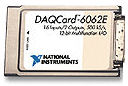
- The AD/DA-board (situated in the left side of the computer) connects to the BNC-2110 connector block via a thick black cable.
- The BNC output labelled "AO 0" on the BNC-2110 connects to the BNC labelled "INPUT"
 at the back of the DigiTimer DS5 (top/left seen from back).
 - The BNC input labelled "AI 0" on the BNC-2110 connects to the BNC labelled "VAS Out" on the grey Visual Analog Scale main box.
- The grey Visual Analog Scale box connects to LED bar via grey 9-pin D-sub cable.
- LED bar and handheld response bar are connected via thin black cable.
Hardware Illustrated
Data Acquisition
 |
 |
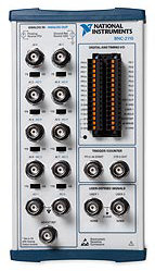 |
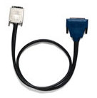
| DAQCard-6062E: A/D and D/A board | Interconnecting cable | BNC-2110: Connector box for the DAQCard |
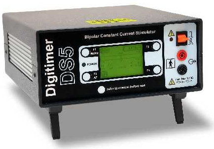
DigiTimer DS5 Electrical Stimulator
 You may want to consult the Operators Manual (PDF).
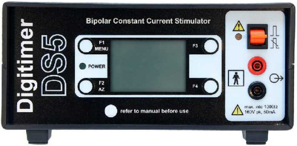
Front view: Electrodes are connected to the sockets in the right hand side.
Note the F-buttons around the central display and the red enable/disable
button top right.
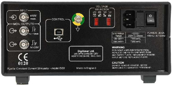
Rear view: Analog input is situated top left.
VAS Meter
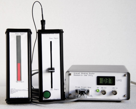
From left to right: LED indicator bar, handheld response bar and Visual Analog Scale main box
| Back to Index | Updated 2009-04-15 20:10 /KnL |