
Users Guide
Isolated Stimulator, NoxiTest IES 230, "NoxiStim" |
Knud Larsen |
Introduction
The NoxiTest IES 230 is an isolated electrical stimulator. It offers mono-polar current controlled electrical stimulation in the amplitude range from zero to 100mA.
Both timing and amplitude of the stimulation can be controlled directly from the front panel of the instrument as well as externally via the TTL and Analog inputs. An overview of the possible modes of operation is given below.
Modes of Operation
| Amplitude Control: | Manual | External |
|---|---|---|
| Stimulus Control: | Man. | Ext. or Ext. scaled see Ext. vs. Ext. scaled |
| Trig | Stimulus is trigged by TTL input or Test button. Duration is set via Pulse Width controls. Amplitude is set via Current controls. |
Stimulus is trigged by TTL input or Test button. Duration is set via Pulse Width controls. Amplitude is set via Analog Input at trig time. |
| Gate | Stimulus is on as long as the TTL input is high*. Amplitude is set via Current controls. |
Stimulus is on as long as the TTL input is high*. Amplitude follows the Analog Input. |
| Analog | Not Available! | Amplitude* follows the Analog Input regardless of TTL input state. |
| *) Within current·time limits | ||
Here follows a description of the front panel controls, sockets, etc. They are divided into -
- Power: Consists solely of an LED indicating if the intrument is powered. Power is turned on/off at the back of the instrument.
- Stimulus Control: Timing
- Amplitude Control: "Strength"
- Isolated output: Polarity and connection to the electrodes
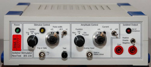
Stimulus Control
Stimulus control is concerned with the timing of the stimulation. The yellow LED indicates an ongoing stimulation.
The Function control offers three modes:
- Trig
- Gate
- Analog
The functionality of the other controls depends on this mode.
The Pulse width controls (knob and switch) sets the duration of the stimulus pulse in Trig mode. This is also true in Gate mode if the Test button is used to trigger the stimulation. In Analog mode these controls have no effect.
The Trig or Gate is a TTL-level BNC input used in Trig and Gate mode: In either mode a transition from low to high initiates (triggers) the stimulation. In Gate mode stimulation will continue until the level returns to low level (or the internal current·time limit is exceeded).
The Test button allows you to manually trigger a stimulation pulse.
Amplitude Control
Amplitude control is concerned with the amplitude of the stimulation, ie. the amount of current the stimulator will attempt to deliver through the electrodes (connected to the isolated output).
The Function control offers three modes:
- Man. ~ Manual
- Ext. ~ External (analog)
- Ext. scaled ~ External scaled (analog)
The Current controls (knob and switch) determine the amplitude in Manual and External scaled mode: In Manual mode the amplitude is solely controlled by the Current controls. They have no effect in External (non-scaled) mode.
In the two External modes the analog signal applied to the Anlog Input BNC will affect the amplitude, as decribed below:
Ext. vs. Ext. scaled
In either mode a zero Volt input applied to the Anlog Input BNC will result in a zero amplitude. The amplitude will increase linearly with the input voltage up till 10V.
In External mode 10V corresponds to 10 or 100mA according to the x1/x10 multiplier switch. An example: 1.3V input will result in a 1.3mA amplitude if the multiplier switch is in the x1 position and 13mA if in the x10 position.
In External scaled mode 10V corresponds to the setting of the Current controls. An example: Assuming the knob is set at 4.2 and the mutiplier switch at x10, then a 2V input will result in a 4.2x10x2/10 = 8.4mA
Isolated Output
This is where you connect the electrodes.
The three-position switch allows you to disable (disconnect) the output, or set the polarity of the stimulation: Positive or Negative relative to the Com socket.
The Out of Compliance LED indicates if the stimulator is not able to deliver the requested stimulus due to a too high electrode impedance. The stimulator can output up til 240V to drive the current through the electrodes. If this is not enough to achieve the requested current then the current will be limited and the LED will flash. As a result the maximum electrode impedance is 2.4kOhm if the full current range of 100mA is required.
Rear panel of the instrument
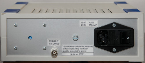
Connect the 230V Line input socket to a 230VAC power outlet with a suitable cable. The instrument is turned on/off via the I/O-switch shown right.
A trigger output, TTL level with a duration of 200µs, is available: The output signal will go high for 200µs when the stimulus current exceeds 200µA (ie. transits from below to above 200µA).
| SMI, Fredrik Bajers Vej 7 D3, DK-9220 Aalborg, Denmark, Tel: +45 9940 8827, Fax: +45 9815 4008, E-mail: Contact-SMI | | | Updated 2009-01-23 |